
December 19, 2013
Blog Updates, December 2013
In addition to a few new posts recently, we've gone through the other pages and made updates throughout. You'll find a totally new Projects page, additional past and present entries on our Appearances page, and a few additions to our Links page. Click on through and see what all we've been up to lately!
December 10, 2013
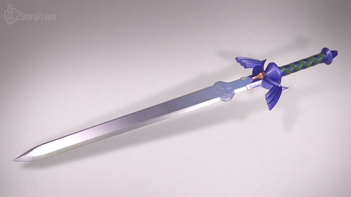
True Master Sword
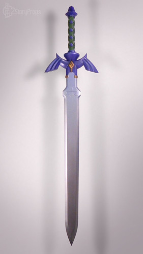
As of this blog entry, the most recent Zelda game to come out is The Legend of Zelda: A Link Between Worlds for the Nintendo 3DS. I have not played it yet, so my would-be opinion of the game does not factor into this at all. My all-time favorite Zelda game is Skyward Sword, and for quite a variety of reasons. I won’t go into them, but it definitely includes my favorite rendition of the Master Sword to date. It’s been on my “want to build” list, but there were just other, more readily-buildable, or more time-sensitive builds I needed to work on. Earlier this year, I was commissioned to build it (that is, what is referred to as the “True Master Sword” in the game), so now I had a need to build it, and I couldn’t be happier!
Anyways, the build isn’t really too much different from my previous Zelda sword builds, except for a few added techniques to achieve certain components. So a lot of this write-up will just highlight certain aspects of it as it’s really nothing new or anything terribly complicated.
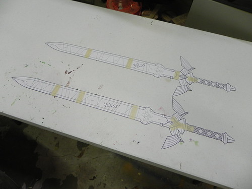
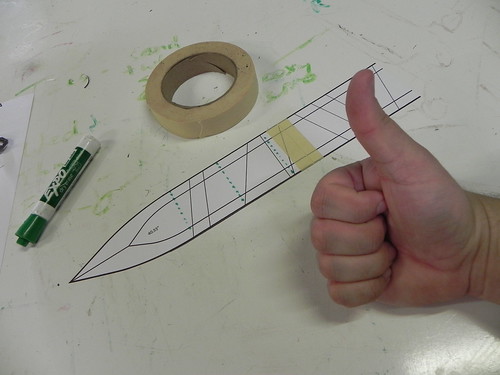
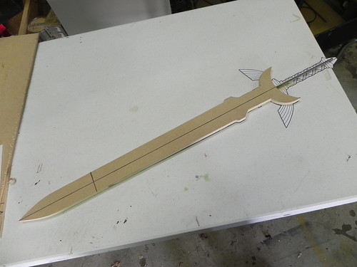
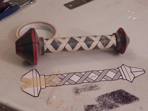
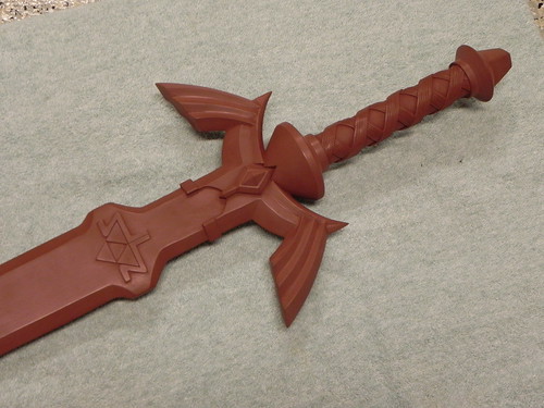
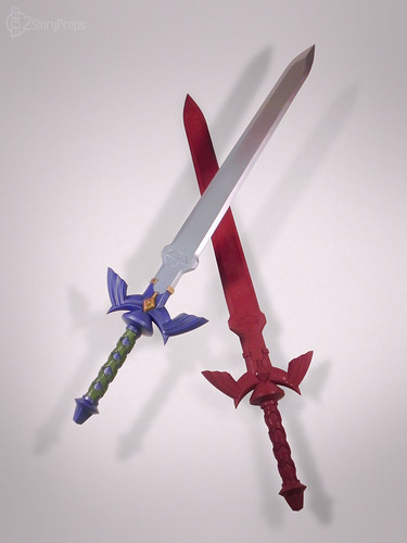
To begin, I drew up some templates. Fortunately, there are lots of great references out there for this, which made drawing my templates easy. Keeping with my desire to make all my Zelda swords in-scale with each other, I landed on a final length of 40.5” long. At first, I thought that would be way too long, so I made a secondary template which had a blade that was 2” shorter. The visual loss was not significant enough to really matter, but in the end, it just didn’t feel right. Besides, it IS a long sword, after all. So I went with the original measurement of 40.5” long.
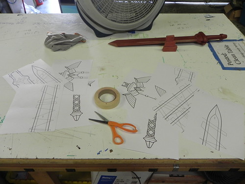
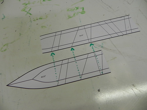
Speaking of my templates, and in case you were wondering, I print all my templates out on regular 8.5” by 11” cardstock. I could very well have them printed at Kinkos or something, but being able to piece it together on the spot makes scaling go a little quicker for me. On most builds, I may go through three or four templates before I decide it’s the right size (that is, if I don’t have anything else to base the measurements on). So in order to get parts to line up correctly, I draw a mess of thinner lines over the template so I can line them up in the light and then tape them together. A little messy, but it works just fine.
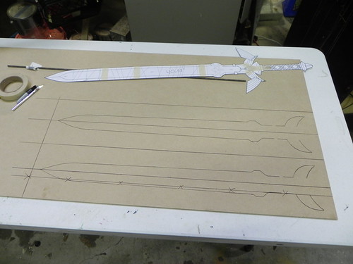
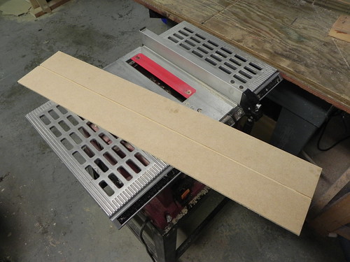
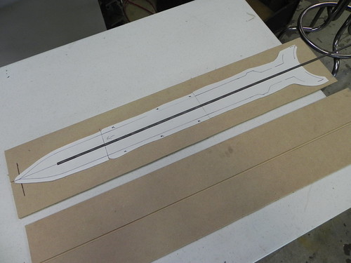
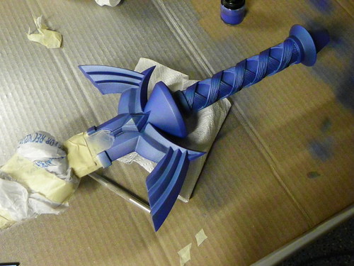
With my templates drawn and cut, I decided what needed to be made out of MDF and what didn’t, and then transferred my templates accordingly. Prior to cutting the templates out in the 1/4” MDF, I ran the MDF down a table saw to draw a central groove down what would become the interior of the blade, into which I would later insert a threaded rod for support later on in the build. Once the interior groove was cut, I decided 1/2” was just barely too thin, so I thickened it up with a layer of 2mm sintra sandwiched between each 1/4" sheet of MDF. I glued the stack together, and then cut it out on a scroll saw, after which I carved in the blade’s edges with my dremel and my power sander.
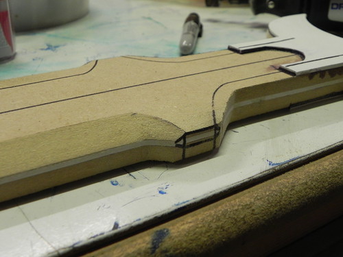
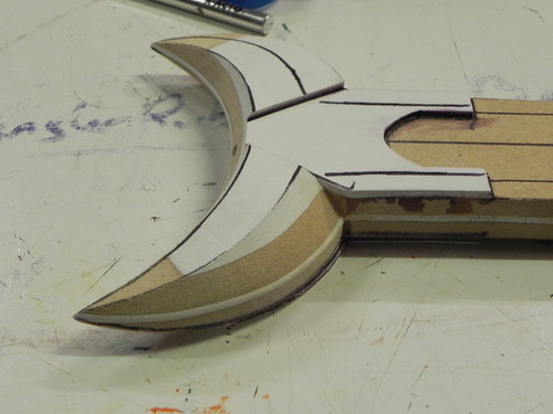
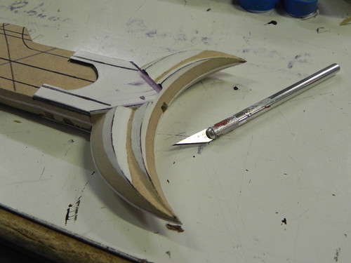
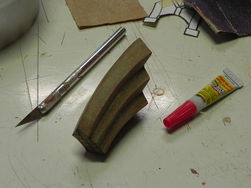
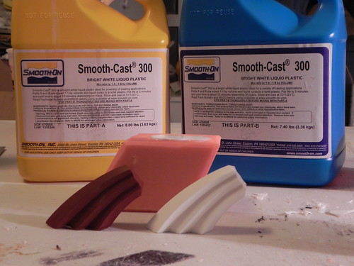
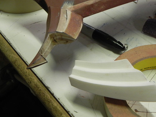
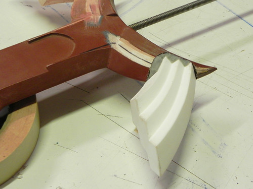
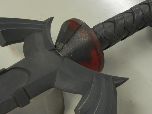
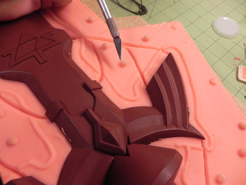
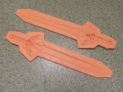
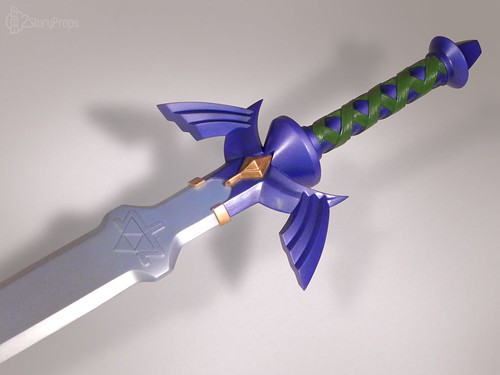
The cross guard proved a little tricky to carve, and there were multiple passes over it to get it just right. But in the end, the shape was actually just carved in with my dremel and an Xacto blade, and then sanded smooth. The wings would have to be added separately, so in order to get them perfectly symmetrical, I sculpted one (again, carved some MDF with my dremel and Xacto blade), made a mold, and cast two copies out of Smooth Cast 300 resin. While it’s a smaller component instead of the full cross guard, it’s the same exact thing I did on the previous Zelda swords to attain perfectly mirrored sides on an otherwise difficult to sculpt component. On a side note: A little trick I picked up from either Jarman Props, Zprops, or Punished Props (I can’t remember which!) is that if you’re working with MDF, coat your carved piece in super glue and let it soak in and dry. It really doesn’t take long, and when you sand it, you get a very hard, very smooth surface with nice, sharp edges. It’s such a neat trick that I used it throughout the build, and I encourage everyone out there following along to try it. You’ll be glad you did! Anyways, once the rest of the cross guard was sculpted, I measured out where the wings would sit according to my templates, and notched out the main cross guard. Then I inserted the wing castings and secured them in place with super glue and Apoxy Sculpt.
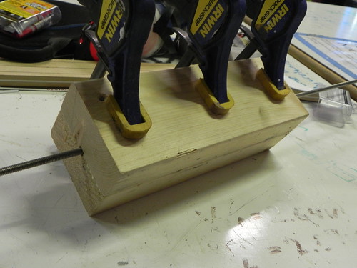
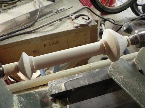
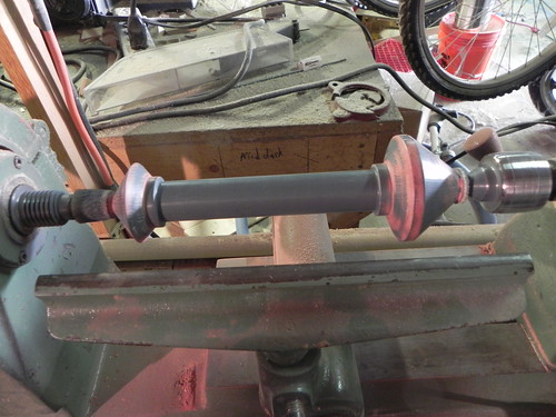
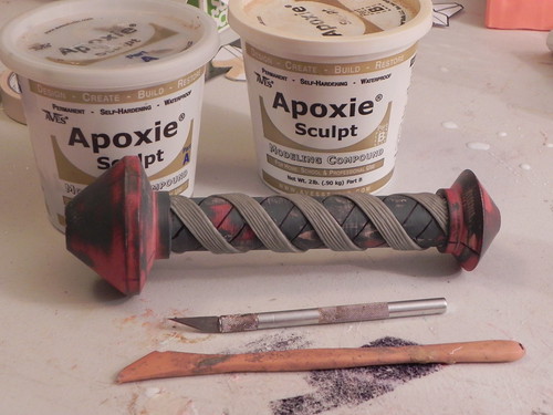
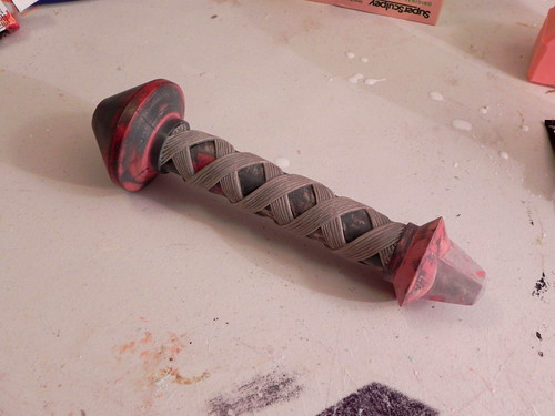
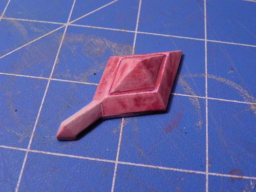
The cross guard wasn’t finished at that point, however, as I still needed to sculpt the jewel. However, before I did that, I needed to have the grip in place. To make the grip, I glued some scrap wood together (with a central groove in each piece of wood, in a similar manner to the blade) and chucked it up on the lathe. Using my template, it really didn’t take too terrible long to turn the grip. While it was on the lathe, I puttied it up and used the lathe to sand it perfectly smooth.
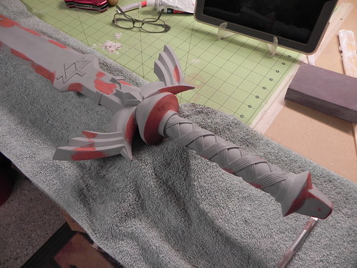
The grip wasn’t ready to install, though, as I still had a substantial amount of sculpting work to do on it. In order to get the grip’s weave feature sculpted, I taped out the wrap pattern on the grip (which was no small feat!), marked it with Sharpie, and removed the tape. Then I sculpted the grip weave on using Apoxy Sculpt. On a side note, I discovered that Skyward Sword’s concept artist intended for the green weave to be a grass-like material, and that really intrigued me. I had to add that feature to the sword. So while I was sculpting the pattern, I carved in several grooves along the bands of Apoxy Sculpt to give it somewhat of a grass-like texture. Separately, I added the pommel by using Apoxy Sculpt as well. Are you seeing a trend here? Apoxy Sculpt is kick ass.
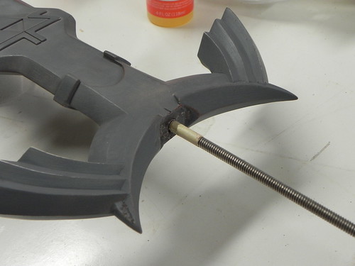
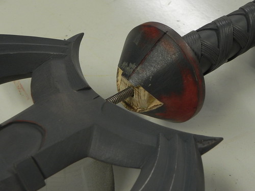
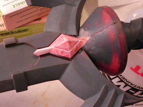
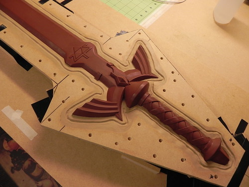
After what felt like working on the handle for weeks and weeks and weeks (which realistically wasn’t the case), I was able to finally attach it to the rest of the sword. Here’s where that threaded rod comes in. gluing the rod into the blade first, I was able to easily line everything up and glue the grip in place. I ended up notching out the cone section of the grip so that it would fit snugly into place along the bottom side of the cross guard. Doing so made it so there was zero guess work in aligning the grip to the rest of the sword. With the grip in place, I could finally finish off the cross guard by adding the jewel. Again, to attain symmetry, I sculpted one jewel, molded it, and cast two copies.
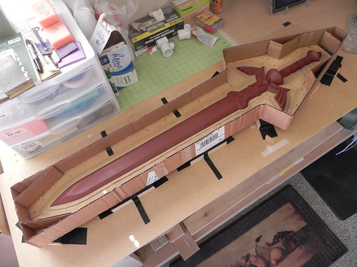
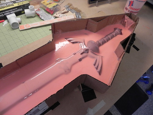
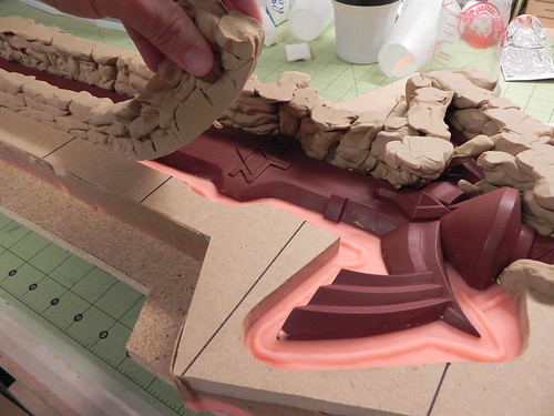
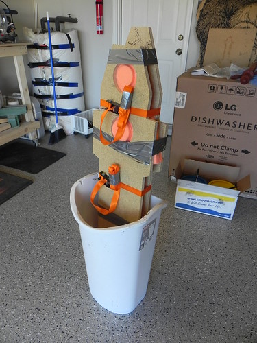
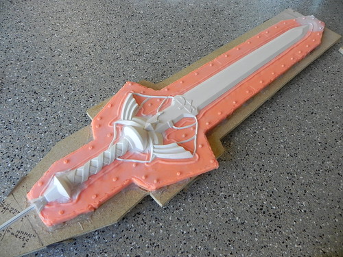
When the final sculpt was cleaned up, it was ready for molding. It actually had a similar molding process to Pipit’s Sword, wherein I used MDF to help with the mold seam and reduce the amount of clay work I had to do. It was pretty standard two-part mold work. My rubber of choice was my go-to Rebound 25, and it took one entire “gallon kit” and most of a “trial kit” of the stuff to get it molded. Like the Goddess White Sword, I had to cut in several vent sprues to allow the resin to fill undercut areas. And like the other Zelda sword molds, the rubber parts in this mold would get clamped between two sheets of MDF during the casting process. In the last photo below, you'll notice that it's sitting in a trash can. The trash can is there in case there are any leaks or overflows during the casting process, so that the spilled resin is retained in the can and not all over my floor.
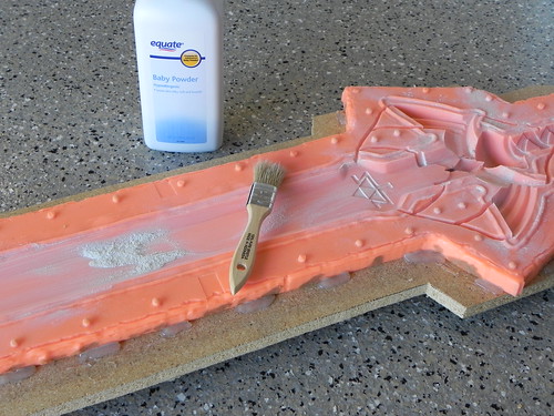
I wanted to try something I picked up from another prop builder, Matt Munson, since I had a lot of sharp edges I needed to capture. It’s not an uncommon trick, though, I just had never done it before, and with all the little shapes and nooks and crannies on this thing, I didn’t want to take any chances with bubbles. Before casting resin into the mold, I brushed in a coat of talc (in the form of baby powder). The talc works itself into all the hard-to-reach areas, and through capillary action, pulls the resin into those areas. This produces a super crisp casting, reducing bubbles that would normally appear in the castings to nearly zero.
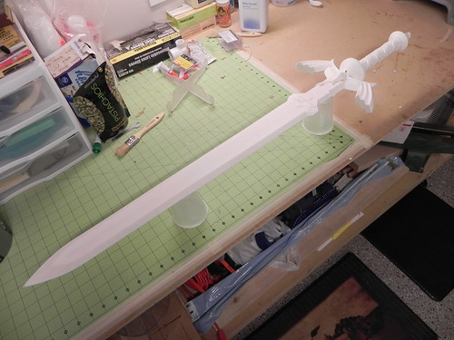
I had some trouble casting this thing. I burned through a couple of castings that kept deforming in bizarre ways. Most resins shrink ever so slightly, and that’s normal. However, on larger items such as this, it can really cause adverse effects, especially if there is something impeding the shrinkage. Initially I had the same metal curtain rod cast into these as I did the Goddess White Sword. However, with the amount of resin the blade caused the weak metal to bend while it shrank, which caused the blades to curve. To fix that, I swapped out the cheapy metal curtain rod for a 3/8” steel threaded rod. The threading provides a mechanical connection to the resin, and the stronger steel prevents any flexing that the resin’s shrinkage would normally cause. The trade off, though, is that the steel rod is much heavier than the curtain rods, so the sword has some weight to it. It’s appropriate weight for being a sword, but it’s a little heavier than one would expect out of something that is made of plastic.
I also switched to a different resin for this sword. My go-to resin is Smooth Cast 300 for it's ease of use and it's quick curing time. It makes casting small things and slush casting helmets really quick and easy. However, it kicks a little too fast for something like this where I need a lot of working time, so I switched to Smooth Cast 305. It's the same exact resin, except that it has an added chemical to it that slows the curing process down, giving you more working time. The downside to it is that it seems degassing it would be beneficial, as there were quite a few air bubbles throughout that needed to be dealt with.
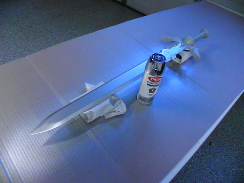
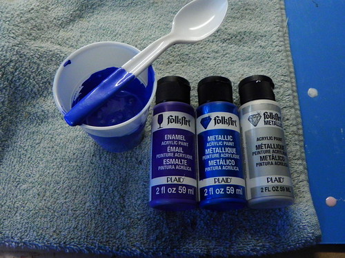
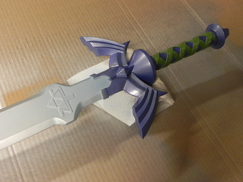
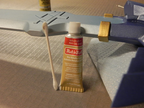
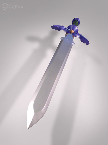
Anyways, after cleaning up the “steel rod” casting, I took to painting it. It wasn’t ever explicitly requested by the customer, but I made an assumption and chose to paint it up like the in-game version instead of the water-colory production artwork. This significantly reduced my painting time, as I was quickly approaching my due date. The blade got some Krylon spray can silver prior to any other paint work. Typically I don’t like using it, but if you let it dry for at least a full day, it doesn’t really retain finger prints. Then, I used my airbrush to apply custom-mixed acrylic paints to the grip. I did several passes over it in slight variations of the color to give it a neat shimmery look in different lighting. Next, I painted the grip weave by hand, and then further accented it with more airbrush work. After the grip was done, I misted some light blue at the base of the blade, fading it out half way up the blade. The jewels were painted in a metallic gold paint for the bulk of the jewels’ surfaces, and then they were coated in gold leaf Rub N Buff. The very slight brush texture from the paint caused the Rub N Buff to buff off in a slightly uneven manner, which gave it this neat, subtle “aged” look to it. To finish everything off, I gave it a couple coats of Spar Urethane clear coat.
This truly was a joy to build, and even though I only had the completed sword in my possession for a few days, the payoff was very rewarding.
Click here to go to the full Flickr photo set:
http://www.flickr.com/photos/2storyprops/sets/72157635205101916/
December 8, 2013
Deadmau5 LED Head v1 (non-LED version)
I don't know off hand how long my blog entries tend to be, but as usual, this is going to be a long one. Get your reading glasses out, folks.
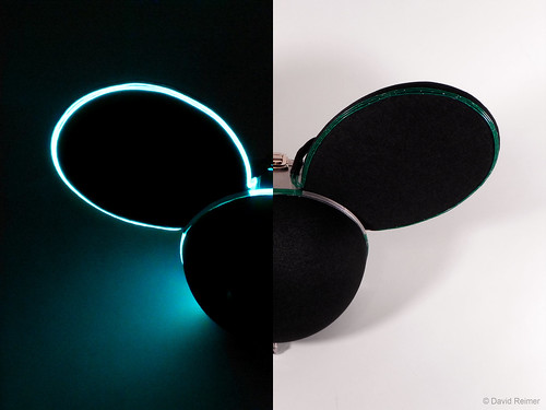
When I decided to first make a replica of Deadmau5's Cheese Head, it was a toss up between making that head and the first LED head. I figured I wasn't ready to build the LED head, so I went for the Cheese Head first. Now, from this point forward, when I talk about the "LED Head," specifically I'm referring to the non-LED version of the first LED head. There were two v1's: the big fancy one with a face full of LEDs that was physically tethered to the stage, and a lighter, non-tethered one without all the LEDS in it. The two were identical except for the lack of LEDS and the lack of the tether. Both had the black cloth ears and face, the EL wire silhouette, the chin-mounted camera, and the metal back with the fold-out fan panel. The one I built is the non-LED version, and there's a reason for that. We'll get to that in a moment.
Thanksgiving day of 2012, I proposed to my girlfriend, and shortly thereafter, Wayne and I got to planning my "bachelor party." I put it in quotes because it wasn't your typical bachelor party. We decided to go see Deadmau5 live, and the only time we could do that before the wedding was to attend Ultra Music Festival in Miami Florida. Both of us wanted to make a new Deadmau5 head for the show, so I used it as an opportunity to build this LED head. Now, the reason why I went without all the LEDs is three-fold: For one, I did not have the time or ability to quickly learn how to design and build my own LED matrix screen; two, such an electronics package would have been a heavy thing to have on my neck at any time, let alone in the heat of Miami, FL.; three, I wanted to be able to see the show, so not having a face full of wires was beneficial. That's the reason the real one has a chin-mounted camera wired to in-helmet screen goggles, so technically there's a work-around for that third factor, but still, attaining as much visibility as possible was key.
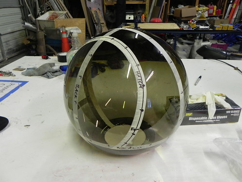
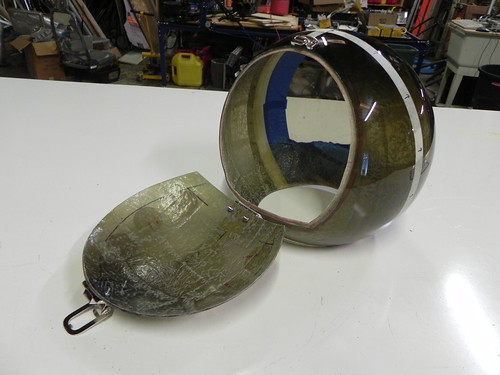
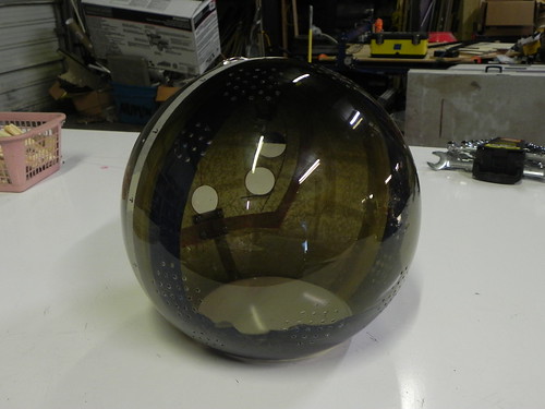
So I ordered my acrylic globe, and took all my notes. My reference material primarily came from the "Live at Earl's Court" Deadmau5 concert video available on iTunes, but I also snagged some behind-the-scenes photos from his Facebook page. There was a lot of planning involved in this, as there aren't really any other Deadmau5 heads like it, so you can't really base it on any other build. Long story short, I taped out all my cut lines on the globe, and prepared to fiberglass the interior of the back half of the globe. The real one is metal, so the back half of the globe would need to be rock-solid in order to provide the necessary structure for the rest of the helmet.
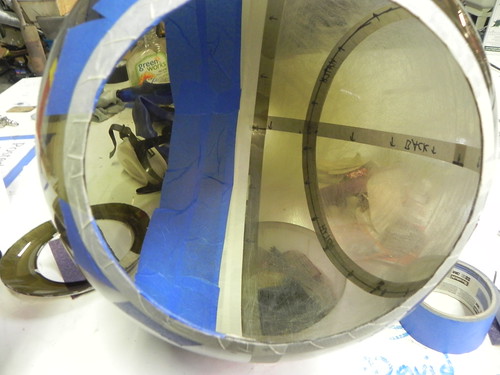
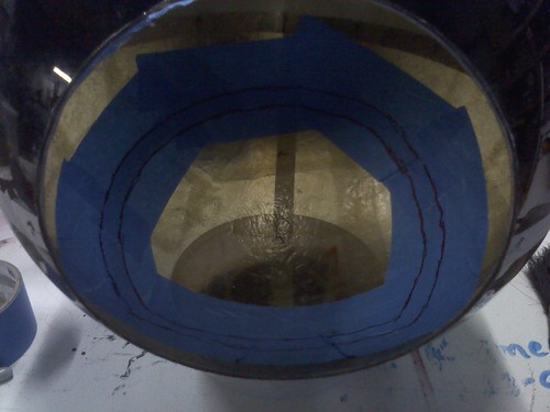
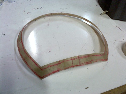
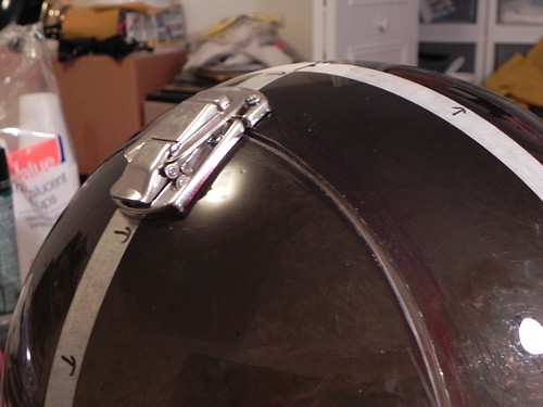
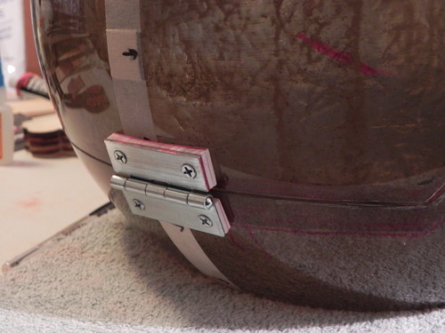
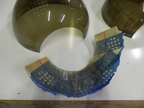
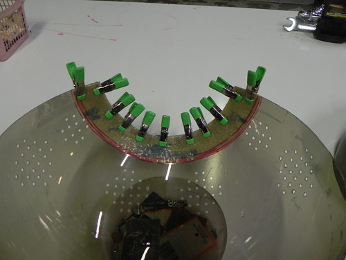
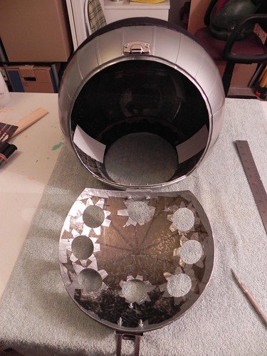
Prior to cutting out the back hatch, I taped off the newly-fiberglassed interior and fiberglassed over the tape in the rough shape of what would become the hatch's inner lip. The tape prevented both layers of fiberglass from bonding to each other, and it allowed me to draw the lip shape (in Sharpie). The fiberglass resin we use is translucent, so having that drawn line there allowed me to cut the lip to shape easily. Once the lip was cut out, it was glued inside the helmet, and my mounting hardware for the hatch was installed.
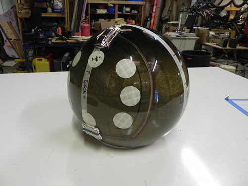
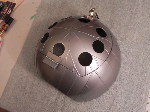
Once the hatch was attached, I mapped out the holes for all the fans. I think I used the bottom of a small Solo Cup or something for the template, but it was one of those trial and error kinds of things getting the size of the holes just right. I made multiples of the template on some tape, and affixed the templates in place. Keep in mind, I was making notes on the globe itself during the whole build. Don't be afraid to draw on your prop as you're building it.
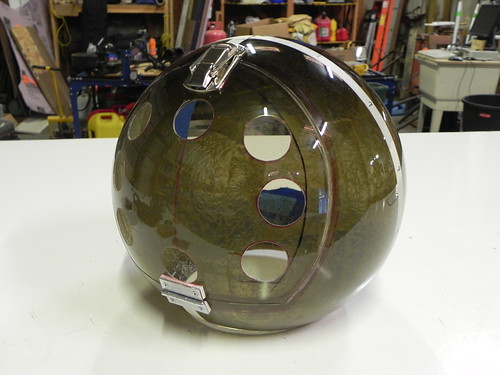
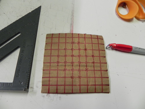
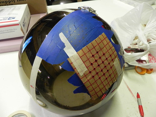
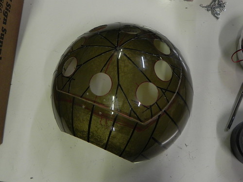
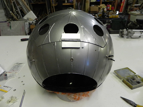
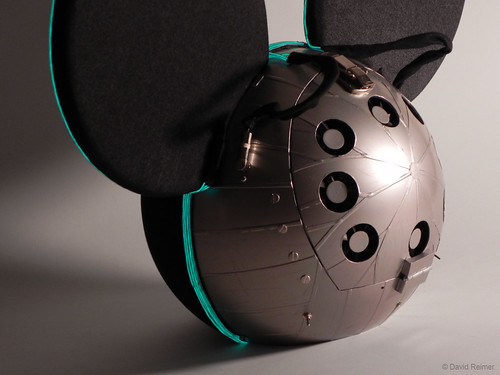
Next came a very nerve-wracking step. So most of the other Deadmau5 heads have great ventilation because you just breathe right through the mouth. This one doesn't have a mouth, so I needed to come up with a means to get air close to my face. There are 8 fans in the back that would blow air in, but having some additional means of getting air in was critical (for times when I would turn the fans off - which actually became critical at UMF because of the second-hand smoke). My solution was to drill a series of hole grids in the front half of the globe. I came up with a template on some cardboard, and transferred that template to the globe, then CAREFULLY drilled the holes. Every time I drilled a hole, I was giving the helmet a new place to potentially crack. In all, there are 160 some odd holes in it, and zero cracks. (After the fact, I decided that all future Deadmau5 heads would be done in polycarbonate, which would eliminate the need to fiberglass the interior because it is WAY stronger and would prevent any sort of cracking).
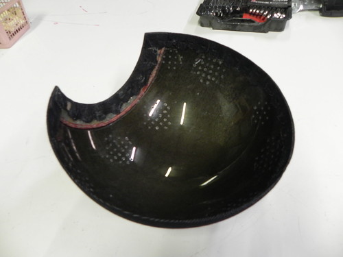
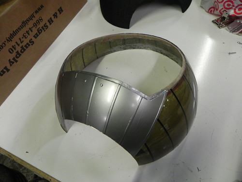
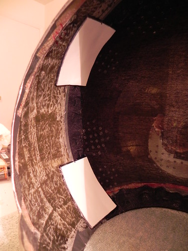
At this point I was ready to cut the front half of the globe off, but I needed a way to add a little bit of strength do it. Remember how I taped off the interior to fiberglass the hatch lip? I did the same thing on the interior of the front half at the neck hole. After cutting that little half-moon to shape, I epoxied it in place.
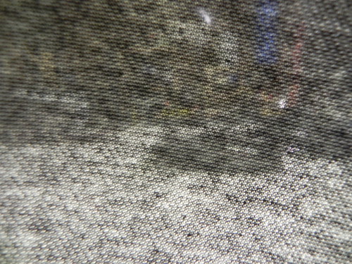
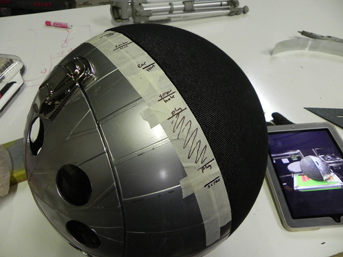
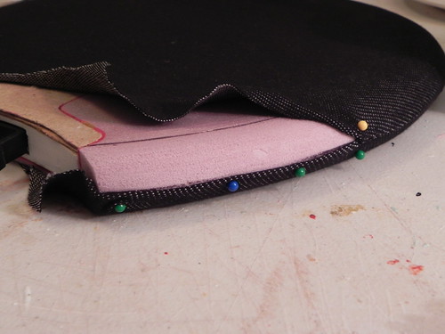
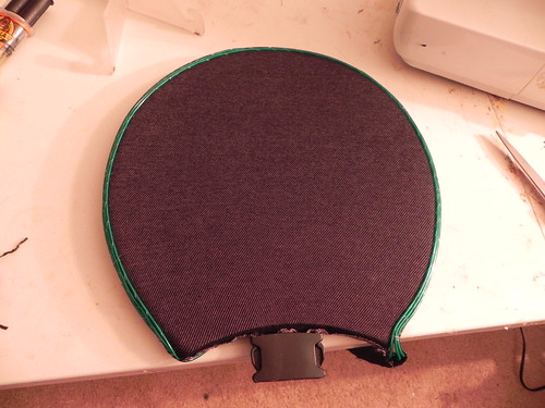
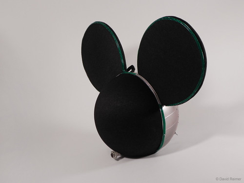
With all the ventilation holes cut and the fiberglass reinforcement installed, I was ready to add the cloth. Now, this was a particular tricky fabric to source, and the fabric that I have isn't even correct. I haven't been able to identify the real stuff at all, but it's some kind of tight-knit, 4-way stretch shimmery/sequiny fabric. The closest I was able to find was "Jeggings" fabric in a black denim. The "denim" part is critical to the look of it, because when it's stretched, the white inner elastic shows through and kind of looks shiny. Anyways, I stretched some of the front half of the globe and clamped it in place. To affix it in place, I removed one clamp at a time, re-stretched it, and hot glued it in place. The visibility is surprisingly pretty good, albeit you are looking through cloth, so it's fuzzy by default. (The third photo below isn't necessarily representative of the true visibility.)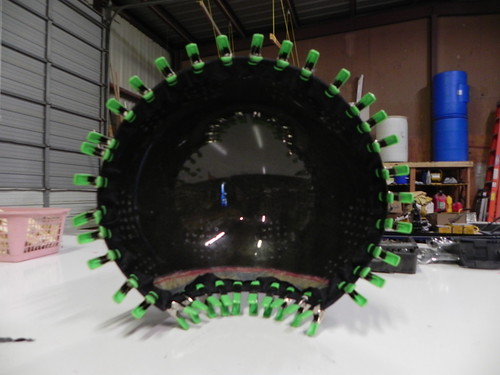
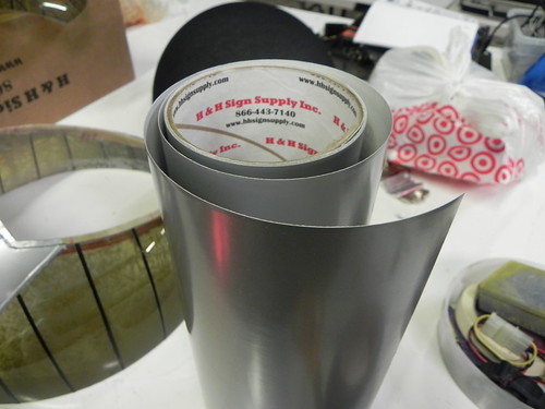
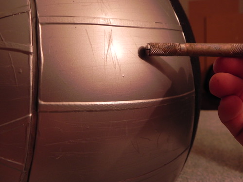
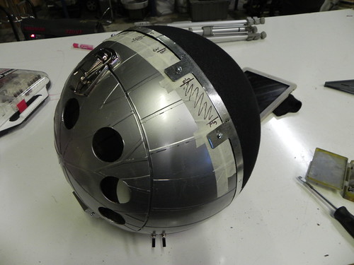
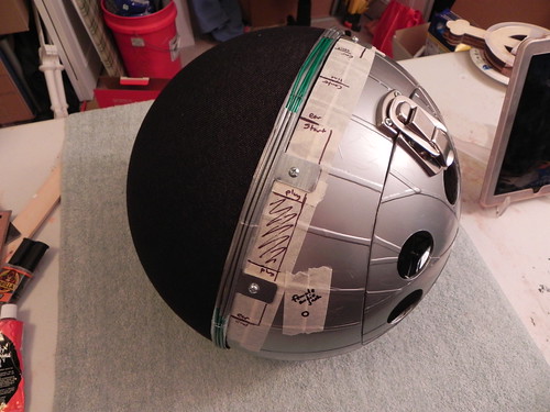
Remember how I said the real LED head is metal? Well, that's definitely an assumption. It sure does look metal, and I currently have no means of making half a globe in metal. So I needed an alternative. My solution was to get some brushed aluminum textured vinyl, and stretch it over the globe. In order to get some little fake "overlaps" to mimic the real head, I first laid out my paneling in thin strips of duct tape. This made it easy to section things, off, but it also provided enough of an "overlapped metal sheet" look. Then, to really drive home the correct look, I scratched up the surface with an old broken Xacto tool handle that I keep on-hand for stuff like this.
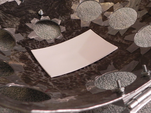
Next, I needed to join the two halves of the globe back together. I cut several rectangles out of some sintra, and heat-formed them to the inner shape of the globe. I didn't want to chance damaging the interior of the front (in case the heat would have some kind of adverse effect on the acrylic, thereby hampering my vision later on), so I used the center of the hatch. Then I glued those in place with industrial hot glue.
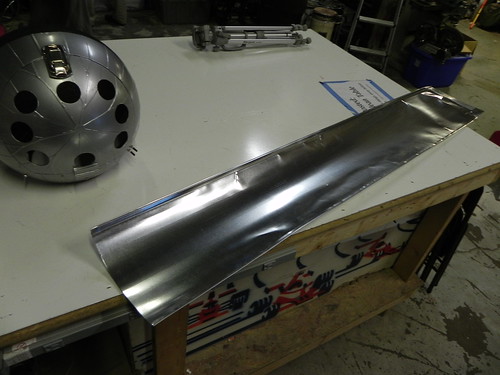
After pausing briefly to work on some of the details on the back (switches, holes, rivets, etc.), I started on the metal frame that would hold the EL wire on. Home Depot doesn't really carry any kind of thin sheet metal, so I purchased a section of aluminum ducting, flatted it out and cut it to shape based on some notes I made on the head. Now that I have finished work on the head, I couldn't really make notes directly on it, so I used masking tape to draw out my metal frame template. This worked well because I could draw it in place on the head, then I could remove the tape and adhere it to the metal and just cut it straight out.
Continuing on the metal frame, I punched several small holes in it though which I was able to stitch clear fishing wire, which was used to hold the EL wire in place. I did this at only a few points along the metal frame, and fishing was on the underside of the metal frame was tied off and duct taped in place. The reasoning for the duct tape instead of glue here is because the color of the wire (unlit) is inaccurate, and I'd like to swap it out for the correct wire at a later time. So I needed a way to remove it later on without redoing a lot of work.

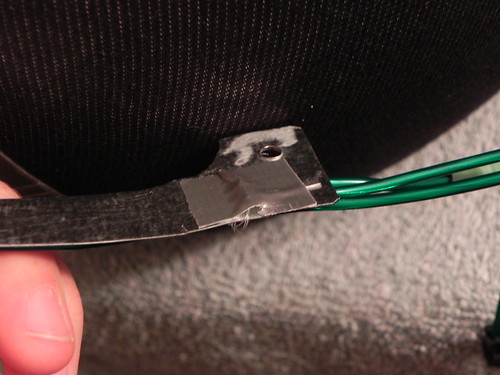
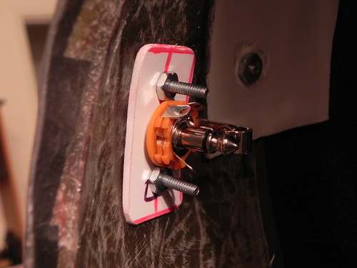
At this point, I was able to start on the ears. On the real helmet, the ears are removable for storage/transport, so the EL wire connects to the globe through some 1/4" audio connectors. I couldn't find the exact model, but what I did find was a quick bolt-in solution.
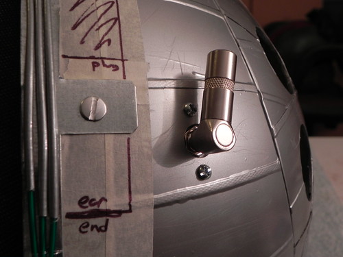
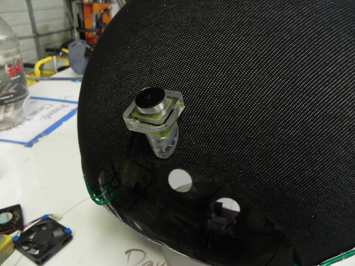
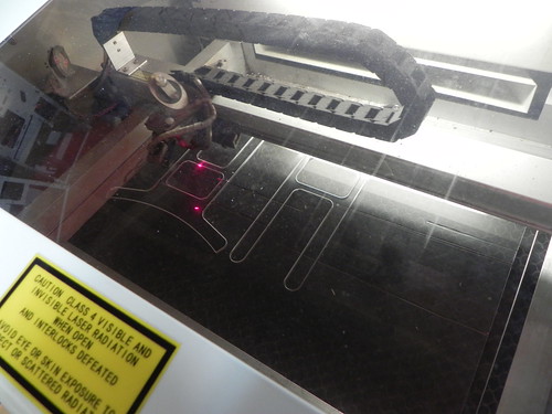
Wrapping up the exterior work on the globe, I laser cut some parts to make a fake camera for the chin. To my knowledge, the real camera's exact make and model are unidentified. And since this is the non-LED version, I didn't need the camera to be real. So some laser cut layers of acrylic glued together attached to a section of clear PVC made for the perfect look.
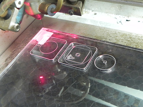
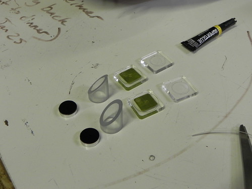
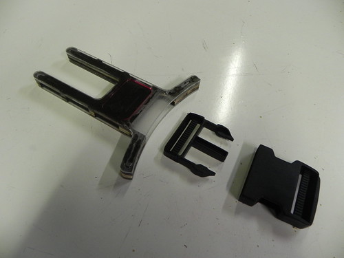
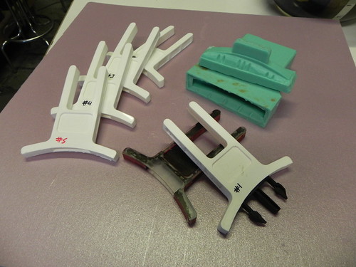
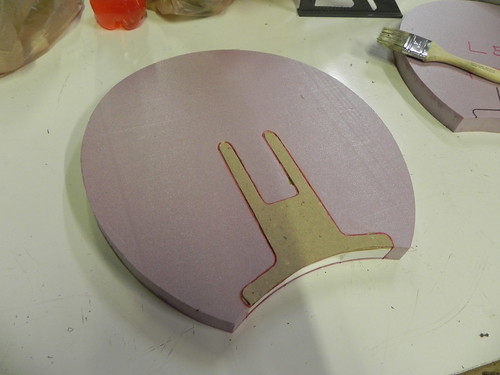
Aside from this whole project not being a typical Deadmau5 head by the nature of it's outward appearance, here's where I really break the fan-build tradition. Most fan made Deadmau5 heads attach the ears with threaded rods bolted to the head. I wanted something a little more accurate to the real deal. I came really close to finding the exact quick-release clips used in the ears, but I couldn't find the correct sizes. With time running out, I made a decision to just design my own ear clip system. It would be molded and cast in resin for repeatability, and it would potentially make for a lighter ear. After several days of developing concept artwork, I used the laser cutter to make my master model for the male end of the ear clip system. After the model was completed, I made a mold of it and produced copies of it in Smooth Cast 300 resin. I didn't need to use the laser cutter on the female end of the clip system, so i just built it out of some sintra. Again, I made a mold of it and cast copies in Smooth Cast 300 resin.
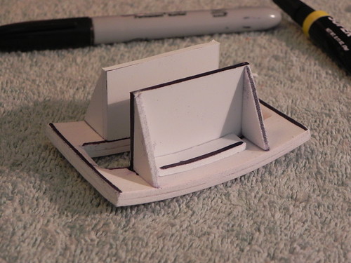
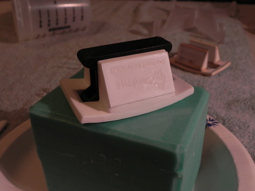
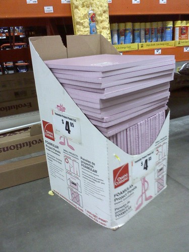
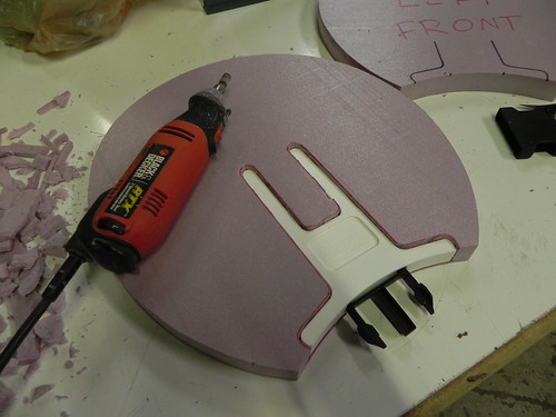
This system doesn't need to be sandwiched between two layers of foam, unlike the old threaded rod method. Instead, you trace the male end onto the foam, and dremel it out. It sounds like a lot of work, but it really didn't take me much more than 5 minutes per ear. Since wood glue doesn't eat the foam, I used it to glue the ear system in place. This also allowed me to use a more accurate, thinner foam. I found these 1" thick 2' foam squares at Home Depot that were perfect. I ended up getting a little overzealous with the dremel, though, so I needed to thicken it back up with some cardboard. Ooops.
Unfortunately, I don't have any photos of the female end of the ear clip system installed inside the head. But basically it's glued in right behind the little slot for the male end. Oddly enough, I can't get any glue to work between the quick-release clip and the Smooth Cast 300 resin, so as of the writing of this blog entry, the female end of the quick clip just slides into place. However, the female end of the ear clip system keeps everything nice and stable.
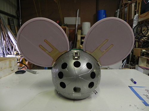
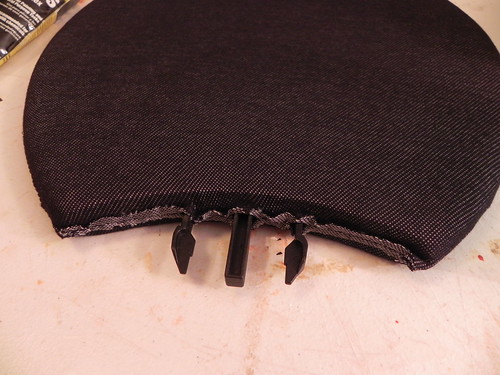
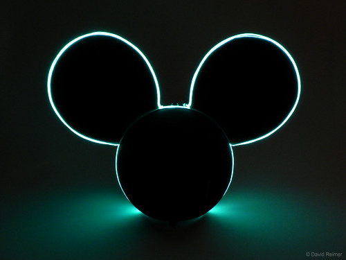
With all the major construction done on the head, I finished up the ears by sewing up a couple "pillow cases" out of the same cloth I used on the globe, and sewed them in place onto the ears. Then, I mapped out the EL wire and sewed it in place with more clear fishing wire. The stock connectors for the EL wire were removed and replaced with the 1/4" audio connectors, and I sewed some little sleeves for the wire, just like the real head. Aside from new connectors, the addition of a switch into the circuit, and a little extra wiring, the EL wire system is relatively unchanged from the stock configuration.
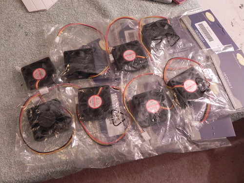
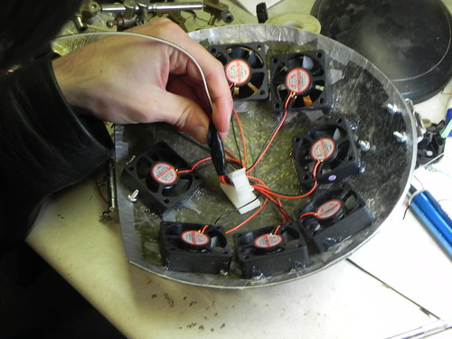
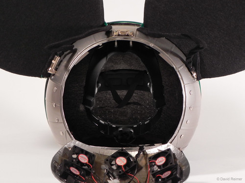
Now I can do some simple electrical wiring, and even some fairly complicated stuff with the proper instructions and diagrams, but when it comes to measuring out all the Volts, Amp hours, and stuff like that for custom projects, I'm like a medieval peasant bewildered by the black magic that is early science. So for the fans, I bought the hardware, gave Wayne an Oreo pie from Burger King, and made him wire it up. Easy peasy. The fans are just hot glued in place, and the wires are all reduced down to a single line going to a battery pack and a switch. Wayne also snipped off all the speed controller wires (the yellow ones) since that was unnecessary in this project.
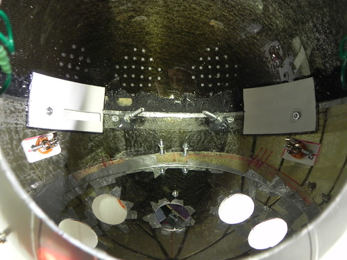
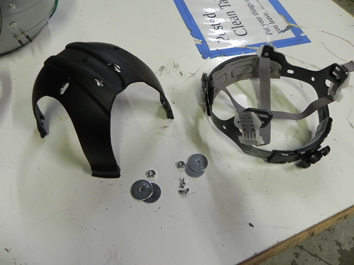
The final component to this build was the inner head gear. According to my references of the non-LED head, the real one is just a trimmed hard hat. The only way I could mount it was to glue in some bolts and repurpose some holes from the hatch's latch system for longer bolts. I thought it was going to prove unstable, but after about 13 hours of hard wear and tear in the Miami heat, jumping around in a mosh pit of drunks, it worked out just fine.
And here are some final photos. You can view more glamor shots, as well as more progress photos in our flickr gallery, which is linked at the bottom of this blog post.
Check out all the photos here!
http://www.flickr.com/photos/2storyprops/sets/72157633129098338/with/8604954376/
When I decided to first make a replica of Deadmau5's Cheese Head, it was a toss up between making that head and the first LED head. I figured I wasn't ready to build the LED head, so I went for the Cheese Head first. Now, from this point forward, when I talk about the "LED Head," specifically I'm referring to the non-LED version of the first LED head. There were two v1's: the big fancy one with a face full of LEDs that was physically tethered to the stage, and a lighter, non-tethered one without all the LEDS in it. The two were identical except for the lack of LEDS and the lack of the tether. Both had the black cloth ears and face, the EL wire silhouette, the chin-mounted camera, and the metal back with the fold-out fan panel. The one I built is the non-LED version, and there's a reason for that. We'll get to that in a moment.
Thanksgiving day of 2012, I proposed to my girlfriend, and shortly thereafter, Wayne and I got to planning my "bachelor party." I put it in quotes because it wasn't your typical bachelor party. We decided to go see Deadmau5 live, and the only time we could do that before the wedding was to attend Ultra Music Festival in Miami Florida. Both of us wanted to make a new Deadmau5 head for the show, so I used it as an opportunity to build this LED head. Now, the reason why I went without all the LEDs is three-fold: For one, I did not have the time or ability to quickly learn how to design and build my own LED matrix screen; two, such an electronics package would have been a heavy thing to have on my neck at any time, let alone in the heat of Miami, FL.; three, I wanted to be able to see the show, so not having a face full of wires was beneficial. That's the reason the real one has a chin-mounted camera wired to in-helmet screen goggles, so technically there's a work-around for that third factor, but still, attaining as much visibility as possible was key.
So I ordered my acrylic globe, and took all my notes. My reference material primarily came from the "Live at Earl's Court" Deadmau5 concert video available on iTunes, but I also snagged some behind-the-scenes photos from his Facebook page. There was a lot of planning involved in this, as there aren't really any other Deadmau5 heads like it, so you can't really base it on any other build. Long story short, I taped out all my cut lines on the globe, and prepared to fiberglass the interior of the back half of the globe. The real one is metal, so the back half of the globe would need to be rock-solid in order to provide the necessary structure for the rest of the helmet.
Prior to cutting out the back hatch, I taped off the newly-fiberglassed interior and fiberglassed over the tape in the rough shape of what would become the hatch's inner lip. The tape prevented both layers of fiberglass from bonding to each other, and it allowed me to draw the lip shape (in Sharpie). The fiberglass resin we use is translucent, so having that drawn line there allowed me to cut the lip to shape easily. Once the lip was cut out, it was glued inside the helmet, and my mounting hardware for the hatch was installed.
Once the hatch was attached, I mapped out the holes for all the fans. I think I used the bottom of a small Solo Cup or something for the template, but it was one of those trial and error kinds of things getting the size of the holes just right. I made multiples of the template on some tape, and affixed the templates in place. Keep in mind, I was making notes on the globe itself during the whole build. Don't be afraid to draw on your prop as you're building it.
Next came a very nerve-wracking step. So most of the other Deadmau5 heads have great ventilation because you just breathe right through the mouth. This one doesn't have a mouth, so I needed to come up with a means to get air close to my face. There are 8 fans in the back that would blow air in, but having some additional means of getting air in was critical (for times when I would turn the fans off - which actually became critical at UMF because of the second-hand smoke). My solution was to drill a series of hole grids in the front half of the globe. I came up with a template on some cardboard, and transferred that template to the globe, then CAREFULLY drilled the holes. Every time I drilled a hole, I was giving the helmet a new place to potentially crack. In all, there are 160 some odd holes in it, and zero cracks. (After the fact, I decided that all future Deadmau5 heads would be done in polycarbonate, which would eliminate the need to fiberglass the interior because it is WAY stronger and would prevent any sort of cracking).
At this point I was ready to cut the front half of the globe off, but I needed a way to add a little bit of strength do it. Remember how I taped off the interior to fiberglass the hatch lip? I did the same thing on the interior of the front half at the neck hole. After cutting that little half-moon to shape, I epoxied it in place.
With all the ventilation holes cut and the fiberglass reinforcement installed, I was ready to add the cloth. Now, this was a particular tricky fabric to source, and the fabric that I have isn't even correct. I haven't been able to identify the real stuff at all, but it's some kind of tight-knit, 4-way stretch shimmery/sequiny fabric. The closest I was able to find was "Jeggings" fabric in a black denim. The "denim" part is critical to the look of it, because when it's stretched, the white inner elastic shows through and kind of looks shiny. Anyways, I stretched some of the front half of the globe and clamped it in place. To affix it in place, I removed one clamp at a time, re-stretched it, and hot glued it in place. The visibility is surprisingly pretty good, albeit you are looking through cloth, so it's fuzzy by default. (The third photo below isn't necessarily representative of the true visibility.)
Remember how I said the real LED head is metal? Well, that's definitely an assumption. It sure does look metal, and I currently have no means of making half a globe in metal. So I needed an alternative. My solution was to get some brushed aluminum textured vinyl, and stretch it over the globe. In order to get some little fake "overlaps" to mimic the real head, I first laid out my paneling in thin strips of duct tape. This made it easy to section things, off, but it also provided enough of an "overlapped metal sheet" look. Then, to really drive home the correct look, I scratched up the surface with an old broken Xacto tool handle that I keep on-hand for stuff like this.
Next, I needed to join the two halves of the globe back together. I cut several rectangles out of some sintra, and heat-formed them to the inner shape of the globe. I didn't want to chance damaging the interior of the front (in case the heat would have some kind of adverse effect on the acrylic, thereby hampering my vision later on), so I used the center of the hatch. Then I glued those in place with industrial hot glue.
After pausing briefly to work on some of the details on the back (switches, holes, rivets, etc.), I started on the metal frame that would hold the EL wire on. Home Depot doesn't really carry any kind of thin sheet metal, so I purchased a section of aluminum ducting, flatted it out and cut it to shape based on some notes I made on the head. Now that I have finished work on the head, I couldn't really make notes directly on it, so I used masking tape to draw out my metal frame template. This worked well because I could draw it in place on the head, then I could remove the tape and adhere it to the metal and just cut it straight out.
Continuing on the metal frame, I punched several small holes in it though which I was able to stitch clear fishing wire, which was used to hold the EL wire in place. I did this at only a few points along the metal frame, and fishing was on the underside of the metal frame was tied off and duct taped in place. The reasoning for the duct tape instead of glue here is because the color of the wire (unlit) is inaccurate, and I'd like to swap it out for the correct wire at a later time. So I needed a way to remove it later on without redoing a lot of work.
At this point, I was able to start on the ears. On the real helmet, the ears are removable for storage/transport, so the EL wire connects to the globe through some 1/4" audio connectors. I couldn't find the exact model, but what I did find was a quick bolt-in solution.
Wrapping up the exterior work on the globe, I laser cut some parts to make a fake camera for the chin. To my knowledge, the real camera's exact make and model are unidentified. And since this is the non-LED version, I didn't need the camera to be real. So some laser cut layers of acrylic glued together attached to a section of clear PVC made for the perfect look.
Aside from this whole project not being a typical Deadmau5 head by the nature of it's outward appearance, here's where I really break the fan-build tradition. Most fan made Deadmau5 heads attach the ears with threaded rods bolted to the head. I wanted something a little more accurate to the real deal. I came really close to finding the exact quick-release clips used in the ears, but I couldn't find the correct sizes. With time running out, I made a decision to just design my own ear clip system. It would be molded and cast in resin for repeatability, and it would potentially make for a lighter ear. After several days of developing concept artwork, I used the laser cutter to make my master model for the male end of the ear clip system. After the model was completed, I made a mold of it and produced copies of it in Smooth Cast 300 resin. I didn't need to use the laser cutter on the female end of the clip system, so i just built it out of some sintra. Again, I made a mold of it and cast copies in Smooth Cast 300 resin.
This system doesn't need to be sandwiched between two layers of foam, unlike the old threaded rod method. Instead, you trace the male end onto the foam, and dremel it out. It sounds like a lot of work, but it really didn't take me much more than 5 minutes per ear. Since wood glue doesn't eat the foam, I used it to glue the ear system in place. This also allowed me to use a more accurate, thinner foam. I found these 1" thick 2' foam squares at Home Depot that were perfect. I ended up getting a little overzealous with the dremel, though, so I needed to thicken it back up with some cardboard. Ooops.
Unfortunately, I don't have any photos of the female end of the ear clip system installed inside the head. But basically it's glued in right behind the little slot for the male end. Oddly enough, I can't get any glue to work between the quick-release clip and the Smooth Cast 300 resin, so as of the writing of this blog entry, the female end of the quick clip just slides into place. However, the female end of the ear clip system keeps everything nice and stable.
With all the major construction done on the head, I finished up the ears by sewing up a couple "pillow cases" out of the same cloth I used on the globe, and sewed them in place onto the ears. Then, I mapped out the EL wire and sewed it in place with more clear fishing wire. The stock connectors for the EL wire were removed and replaced with the 1/4" audio connectors, and I sewed some little sleeves for the wire, just like the real head. Aside from new connectors, the addition of a switch into the circuit, and a little extra wiring, the EL wire system is relatively unchanged from the stock configuration.
Now I can do some simple electrical wiring, and even some fairly complicated stuff with the proper instructions and diagrams, but when it comes to measuring out all the Volts, Amp hours, and stuff like that for custom projects, I'm like a medieval peasant bewildered by the black magic that is early science. So for the fans, I bought the hardware, gave Wayne an Oreo pie from Burger King, and made him wire it up. Easy peasy. The fans are just hot glued in place, and the wires are all reduced down to a single line going to a battery pack and a switch. Wayne also snipped off all the speed controller wires (the yellow ones) since that was unnecessary in this project.
The final component to this build was the inner head gear. According to my references of the non-LED head, the real one is just a trimmed hard hat. The only way I could mount it was to glue in some bolts and repurpose some holes from the hatch's latch system for longer bolts. I thought it was going to prove unstable, but after about 13 hours of hard wear and tear in the Miami heat, jumping around in a mosh pit of drunks, it worked out just fine.
And here are some final photos. You can view more glamor shots, as well as more progress photos in our flickr gallery, which is linked at the bottom of this blog post.
Check out all the photos here!
http://www.flickr.com/photos/2storyprops/sets/72157633129098338/with/8604954376/
Subscribe to:
Posts (Atom)